ST-8E Shutter Error and Correction
John Smith
My ST-8E was showing occasional shutter errors, especially on long unattended scripts. Not being anxious to send the camera back, I called SBIG customer service and they were willing to describe the fix to me.
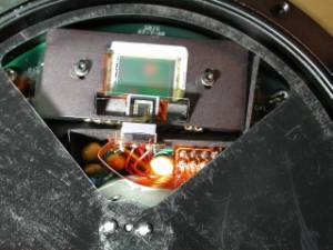
The shutter position is sensed by an emitter-detector optical detector that senses reflection from a piece of aluminum tape that is attached to the inside front cover of the camera. The shutter consists of a large thin disk with two openings opposite each other. The shutter opening that is opposite the main CCD imager allows or interrupts the detection of this reflection opening as the shutter rotates. The intent of the correction is to move the reflector closer to the detector to increase the signal.
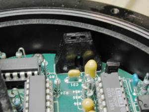
Shutter detector Improved shutter reflector
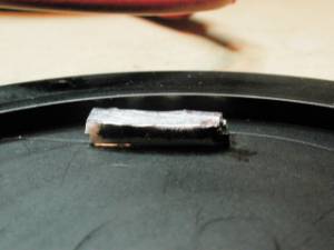
In order to reduce the shutter error, SBIG suggested moving the aluminum tape reflector closer to the shutter detector. The reflector is located on the inside of the bottom of the front cover of the camera. It was suggested to move it up to .15” closer, in order to provide a larger signal to the detector. Adding two thicknesses of foam tape on the existing aluminum tape and then sticking an additional piece of aluminum tape at the top of the stack accomplished this. I made sure the height of the stack was still comfortably below the surface of the cover, in order not to impede the shutter rotation. I was warned that this might lead to shutter detector light being reflected into the main CCD detector. The path was off the right angle prism that is used for the tracking detector, up on to the filter then reflected back off the filter and thence to the detector.
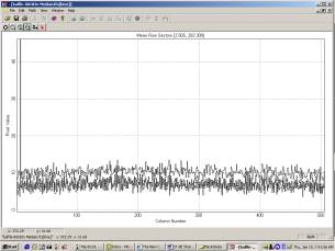
This apparently happened. The following profiles show the brightest areas. The data was obtained by taking 9 light frames with each filter and with the telescope lens cap on. All frames were 5-minute exposure at 3x3 binning and –20 °C. 9 dark frames were median combined and applied to each of the light frames. The light frames were median combined for each filter.
In the curves below, the highest peak was that of the red filter, next was the green, then the blue then the clear. These curves were taken in Mira AP.
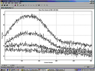
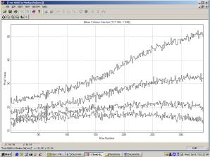
Peak row scan Peak column scan
To get a handle on the maximum difference of the signal, I used the aperture tool in MaxIM DL scanned the areas of maxima and minima. The following table illustrates the result:
Filter Maximum Minimum Difference (ADU) Difference (e/second)
Red 51 19 32 0.33
Green 33 14 29 0.30
Blue 22 12 10 0.10
Clear 18 10 8 0.08
In looking at a bright light reflected from the filters, the intensities above seem reasonable, i.e., the red and green reflect the greatest and the blue less and the clear the least. I suspect AR coatings on the filters would minimize this issue. These are extremely small values, indicating the sensitivity of the detector. Nevertheless this will affect camera data and should be corrected.
It was suggested that, should this reflection situation occur, a light baffle be added to shield the prism from as much light as possible but still not impede the view of the tracking CCD through the prism to the telescope and to not be high enough to impede the shutter rotation. It was also recommended that appropriate static precautions be taken, as I would be working around sensitive electronics. A wrist strap was connected to the camera fan guard and worn at all times.
Two light baffles as illustrated below were fabricated using manila folder material that had been “painted” with a black, permanent felt pen. These were placed on either side of the tracking CCD and formed to go around components as required. The baffles were tack-glued to the top of nearby orange tantalum capacitors.
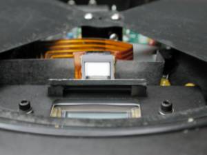
Baffle, top view Baffle, front view
The desiccant was then baked at 350 °F for 4 hours and the camera reassembled. Using the same data as above, 9 sets of images for each filter with 9 dark frames, the following results were obtained.
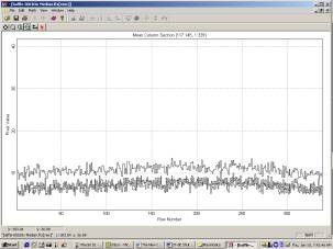
Row scan Column scan
The above data for all four filters shows the same regions as prior to installation of the baffles. There is no sign of spurious illumination of the imager. Aperture scans for maxima and minima gave the following results:
Filter Maximum Minimum Difference (ADU) Difference (e/second)
Red 12 8 4 0.04
Green 8 5 3 0.03
Blue 9 5 4 0.04
Clear 8 5 3 0.03
In all cases, the maxima occurred toward the center of the imager and the minima occurred at the extreme edges. There was no discernible area of brightness in either Mira or MaxImDL as the fields were examined.
Conclusions
Decreasing the distance of the reflecting tape from the shutter optical detector seems to eliminate the shutter errors that occasionally happened. The fix did result in reflected light from the optical detector getting into the main imager. This was satisfactorily eliminated by the installation of small baffles. The resultant dark fields showed little or no sign of spurious illumination
Special thanks goes to Jay at SBIG Customer Service for describing the problems and the solutions. I appreciated not having to send in my camera and was willing to spend the 1 hour or so do it myself. The evaluation images were done overnight while clouds were firmly in place, so no time lost.
John Smith
January 10, 2001
Tucson, AZ